Provides a high-level overview of the key features and benefits of Newson Gale’s range of static grounding solutions.
Provides a high-level overview of the key features and benefits of Newson Gale’s range of static grounding solutions.

This article is designed to aid engineers, operations managers, and safety professionals in understanding the root causes of static electricity and why it can be a potential ignition source in daily operations. The article will also provide a general overview of legislation and industry guidance relevant to static electricity and then outline practical methods around how it can be managed.
High levels of safety awareness in the intermediate and specialty chemical industry have been in place for decades, and the management and mitigation of ignition source risk has always been a major practice for safety professionals, operations managers, and engineers.

Static electricity is just one of several sources of ignition regularly identified as being responsible for the ignition of combustible atmospheres (gas and/or dust), and there are a range of site-wide operations that can result in the generation of static electricity.
Whether the operation involves filling, dispensing flammables, or conveying/tipping powders into vessels, static electricity can be generated just through the movement of the material being processed or handled.
Because static electricity has long been known to present an ignition source in hazardous location operations, it is highlighted in legislation.
In Annex II of the ATEX Directive 2014/34/EU, it states the following:
Section 1.3.2 “Hazards arising from static electricity”
“Electrostatic charges capable of resulting in dangerous discharges must be prevented by means of appropriate measures.”
In carrying out the obligations laid down in Articles 6 and 9 of Directive 89/391/EEC, the employer shall assess the specific risks arising from explosive atmospheres, taking account at least of:
“the likelihood that explosive atmospheres will occur and their persistence,
the likelihood that ignition sources, including electrostatic discharges, will be present and become active and effective,
the installations, substances used, processes, and their possible interactions,
the scale of the anticipated effects.”
Explosion risks shall be assessed overall.
Although it is easy to understand why static electricity can be perceived as a mysterious topic to get to grips with, the principles around which static electricity can present an ignition source risk are relatively straightforward.
One common denominator is the interaction of electrically insulating materials (materials that have a low conductivity, e.g., toluene) with electrically conductive materials (e.g,. plant equipment constructed from metals).
When an insulating material like toluene comes into contact with metal plant equipment, whether it’s flowing in piping, through a filter, or being deposited into a drum, the toluene attracts electrons from the metal surface of the equipment it is in dynamic contact with.
The net result of this interaction is that the toluene is rapidly building a negative electrical charge, as it is attracting negatively charged electrons from the conductive metal, while the metal equipment is rapidly building a positive electrical charge.
The problem with this situation, if it is allowed to continue, is that the voltage of both materials will rise rapidly if both materials are “isolated” from the earth.
| Static accumulating liquids | Static accumulating powders |
| Benzene | PTFE |
| Diesel | Polyethylene |
| Gasoline | PMMA |
| Light crude | Wood |
| Crude/Gas condensates | Polyurethane |
| Jet fuel | PVC |
| Kerosene | Pyrex |
| Toluene | Neoprene |
| Xylene | Nylon |
| Hexane | Polypropylene |
| Heptane | Polystyrene |
Any object isolated from the earth can be described as possessing an “electrical capacitance” which is denoted with the symbol “C” and is measured in Farads.
If we take the example of the toluene building a continuous negative charge as it flows through the metal piping system and gets deposited into an object like a metal drum, which, in this example, is isolated from earth, the drum will build a negative charge on its outside surface.
The reason for this is that the negative voltage of the toluene forces the electrons in the drum to the outside surface of the drum. This is caused by the “rule-of-thumb” principle that like charges repel and unlike charges attract.
The problem with this scenario is that the voltage of the drum will rise based on the amount of negative charge residing on its outer surface relative to its own value of capacitance.

Negative electrical charges distributed on external surface
The more charge, the higher the voltage. This scenario can be best explained through the formula:

(Source: NFPA 77: 6.3.1)
As more charge is deposited on the isolated object there is a constant voltage rise. In our example, this is the outside surface of the drum as it is being filled with the toluene.
| Item | Capacitance (pF) |
| Tank Car | 1000 |
| Automobile | 500 |
| Person | 100 to 300 |
| Oli/Solvent Drum | 10 to 100 |
| Metal Scoop | 10 to 20 |
| Needle Electrode | 1 |
| Dust Particle | 10-7 |
Table 2: Capacitance of objects routinely used in the movement and containment of hazardous products. (Source: Table A.3.3.5 from NFPA 77)
As the voltage rapidly rises and the electrical field strength around the surface of the drum passes 3000 volts per millimeter (the breakdown voltage of air at ambient conditions), there is a real risk that an electrostatic spark will be discharged from the surface of the drum into the potentially combustible atmosphere.
In order to initiate combustion of the atmosphere, assuming it is within its ignitable range, the energy of the resulting spark must exceed the Minimum Ignition Energy (MIE) of the surrounding flammable atmosphere.

The potential energy of an electrostatic spark discharge can be illustrated in the formula:

(Source: NFPA 77: 6.9.1)
If it is assumed that the voltage of the object has exceeded the breakdown voltage of the surrounding atmosphere and is charged to a voltage of, say, 10,000 volts at the moment when there is a spark discharge to another object in close proximity to the drum, the potential energy of the resulting spark would be approximately 2.5 mJ.
This assumes the drum has a minimum capacitance of 50 pF as indicated in Table 2. If we are assuming that the flammable mixture surrounding the drum is a toluene-air vapor, the minimum ignition energy would be in the region of 0.24 mJ (source: Table B.1 of NFPA 77 “Recommended Practice on Static Electricity” (2024)) then the resulting energy from the spark would be capable of initiating combustion of the vapor.
Charge generation is not just limited to liquids. Powder processing operations can produce electrostatic charging rates well in excess of liquids and gases.
In the intermediate and specialty chemicals sector, there are many processes that can result in the generation of static electricity as a natural by-product of the process in question. Such examples include, but are not limited to:


| Charge build up on powders | |
| Operation | Mass charge density (μC kg1) |
| Triboelectrical powder coating | 10,000 to 1,000 |
| Pneumatic conveying | 1,000 to 0.1 |
| Micronizing | 100 to 0.1 |
| Grinding | 1 to 0.1 |
| Scroll feed transfer | 1 to 0.01 |
| Pouring | 1 to 0.001 |
| Sieving | 0.001 to 0.00001 |
Table 3: Charge build up on powders through different processing techniques and the quantity of charge typically carried per kilogram of powder.
(Source: Table 15.3.2 of NFPA 77)
However, the vast majority of these situations can be managed by ensuring the objects at risk of static charge accumulation are not isolated from earth. Because fixed plant, like large storage tanks and vessels, should be grounded via the plant structure, the risk of static spark discharges is most pronounced for moveable objects ranging from tanker trucks to people.
Table 4 highlights some of the sources of electrical isolation on movable equipment. If the objects are connected to ground, then the charge imbalance on the object is neutralized, which mitigates the risk of a static spark with enough energy to ignite potentially combustible atmospheres.
| Objects | What causes capacitance? |
| Portable drums | Protective coatings, product deposits, rust. |
| Tanker trucks/tank trucks | Rubber tires. |
| Piping | Rubber and plastic seals, anti-vibration pads and gaskets. |
| Railcars | Grease, vibration pads isolating tank from railcars. Rails isolated from loading gantry. |
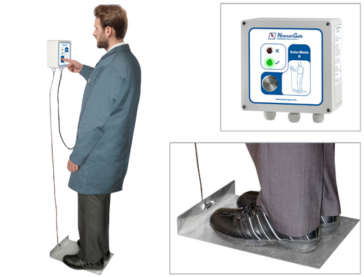
| People | Soles of footwear. |
| Scoops | Rubber gloves. |
| Hoses | Broken internal helixes and bonding connectors. |
| FIBC | Non-conductive fabric/damaged static dissipative threads. |
Table 4: Examples of why process equipment and people can be isolated from earth
Grounding potentially isolated equipment should be regarded as a compulsory safety function in any process and location where combustible products are handled and processed. It is the most practical and effective way of mitigating the accumulation of static electricity on equipment (and people).
However, having objects in contact with the ground is not grounding. For example, resting a drum on concrete or using drag chains on tanker trucks does not provide an effective and reliable means of preventing static charge accumulation.
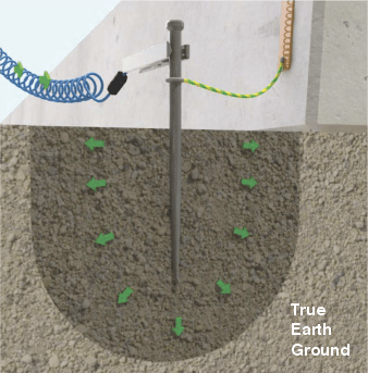
So, what does “grounding” really mean? In effect, if we can connect our potentially isolated equipment to a verified “true earth ground” i.e. a connection to the general mass of the earth that has been measured and verified to be below 10 ohms, in accordance with a standard like the EN 62305 standard for grounding lightning protection systems, we can be confident that connecting to installed ground networks like the local lightning and electrical earthing protection system will enable static charges dissipate safely from the process equipment. The bus-bar network that feeds out from the ground rods (installed ground network) can provide a means of grounding our process equipment.
Bonding is different from grounding in that it ensures that two bonded objects at risk of static charge accumulation are at the same electrical potential; however, it does not mean they have no charge, i.e., are at ground potential (0 volts). Bonding ensures there is no risk of static spark discharges between the two bonded objects. It does not mean they are not capable of discharging sparks to other objects or personnel that are at a lower electrical potential.
NFPA 77, Section 7.4.1.3.1 (2019 ed), “Recommended Practice on Static Electricity”
“Where the bonding/grounding system is all metal, resistance in continuous ground paths typically is less than 10 Ohms. Such systems include those having multiple components. Greater resistance usually indicates that the metal path is not continuous, usually because of loose connections or corrosion. A permanent or fixed grounding system that is acceptable for power circuits or for lightning protection is more than adequate for a static electricity grounding system.”
NFPA 77, Section 7.3.1.6.1 “Bonding and Grounding” states:
“Where the bonding/grounding system is all metal, resistance in continuous ground paths is measured to verify mechanical integrity. (See A.3.3.2.) Such systems include those having multiple components. Greater resistance usually indicates that the metal path is not continuous, usually because of loose connections or corrosion. A permanent or fixed grounding system that is acceptable for power circuits or for lightning protection is more than adequate for a static electricity grounding system. Static grounds should be made to the building steel, if possible. Grounding to power grounds or lightning protection systems is not recommended.”
A.3.3.2 Bonding
“A resistance not exceeding 10 ohms for copper wire or 25 ohms for stainless steel or other metals is typically found in practice. Higher resistances could indicate a lack of mechanical integrity.”
For movable metal objects, this extract from IEC TS 60079-32-1 “Explosive atmospheres, Electrostatic hazards, guidance” recommends the following:
Section 13.4 “The establishment and monitoring of earthing systems”
13.4.1 Design
“Permanent bonding or earthing connections should be made in a way to provide low resistance during its lifetime, e.g. by brazing or welding. Temporary connections can be made using bolts, pressure-type earth clamps, or other special clamps. Pressure-type clamps should have sufficient pressure to penetrate any protective coating, rust, or spilled material to ensure contact with the base metal with an interface resistance of less than 10 Ω.”
A resistance of 10 ohms or less refers to the resistance between the object requiring static grounding protection and the local ground network.
Any resistance higher than this value would indicate loose connections or corrosion (see NFPA 77 Section 7.4.1.3.1), which could limit the dissipation of electrostatic charges from the equipment undergoing electrification.
The challenge, however, is to ensure we implement a consistent and reliable means of connecting to these networks, especially since most of the equipment we are dealing with is portable and will not have a permanent connection to the site’s local ground network.
The implementation of a consistent and repeatable way of grounding mobile equipment needs to take into account the characteristics of the process, who the responsible people are for performing the grounding and bonding safety function on a daily basis, and other factors like environmental conditions and the classification of the hazardous location.
Whatever method is adopted, it is critical to ensure that the person (people) responsible for performing the safety function of grounding equipment understand the importance of doing it and that the grounding activity itself is kept relatively simple.
There are many cases where sites with good grounding practices have been caught out, either due to forgetfulness on the part of an operator or because a minor flaw in the process has been missed.
Grounding clamps (passive) are the most “traditional” means of connecting mobile plant equipment to verified grounding points. However, equipment specifiers need to be aware of the difference between clamps like alligator clips as compared with static grounding clamps that have been designed for static dissipation and repeated use in harsh industrial environments.
Clamps like alligator clips are designed to be attached to clean surfaces like battery terminals. They are not designed to penetrate industrial-grade protective coatings or product deposits on equipment that would otherwise not permit static charges to pass through them. So even though the clamp may be attached to the object, it does not mean it is effectively grounding it.
Clamps that combine a strong spring pressure with sharp, rugged teeth have a greater chance of penetrating surfaces that would otherwise prevent a reliable electrical and mechanical connection (metal to metal) to the equipment undergoing electrification by electrostatic charging.
Clamps that carry the FM approval mark will have passed a range of functional tests that demonstrate key functional performance characteristics to operate successfully.
Although the use of a basic (passive) grounding clamp will not verify a low resistance connection to equipment for the operator, selecting a grounding clamp that combines FM approval with a set of sharp teeth capable of penetrating layers that would otherwise inhibit static charge transfer will enhance the likelihood of repeatable and reliable ground connections to plant equipment.


Combining certified grounding clamps with a ground monitoring system adds the benefit of providing positive confirmation to operators that a 10 ohm or less connection to the plant equipment requiring static grounding protection has been achieved after they have attached the grounding clamp. This effectively removes the “guesswork” out of knowing whether or not the equipment is grounded. Once a connection of 10 ohms or less has been verified by the system, an indicator like a flashing green LED will let the operator know that they can proceed with the operation (e.g., filling or mixing operation).
The benefit of the flashing green LED principle is that it lets people in the location know that the system is continuously monitoring the health and effectiveness of the grounding circuit and that, should the resistance rise above 10 ohms, or the clamp’s connection to the equipment be compromised in any way, the LED will switch off. This will notify people working in the location that the process should be halted, or if it cannot be halted, that the equipment should not be approached until an adequate charge relaxation time period has been adhered to after the process has finished.
The use of a ground circuit monitoring system with a visual indicator has the added benefit of becoming a core step in the operator’s Standard Operating Procedures (SOP), so that if the green light is not obtained, the process should not begin. It also enhances the site’s ability to demonstrate compliance with the recommendations of NFPA 77 and IEC TS 60079-32-1 by ensuring the process does not start unless a verified 10 ohm or less connection has been achieved.

If the process that causes charge generation is automated, an alternative option is to specify a grounding system that will not only verify and visually indicate a ground connection resistance of 10 ohms or less, but through its volt-free contacts, control the process (e.g., tanker trucks loading operation).
Unless the grounding system detects a 10 ohm or less connection, it will not permit the process to begin.
It should be borne in mind that if the grounding system is interlocked with devices to control the flow/movement of material, although the device causing material movement (e.g., pump) may have stopped (e.g., through accidental removal of the clamp mid-transfer), there could be a period of time before the flow or movement of material stops completely.
It is the responsibility of the customer to determine what measures need to be in place to manage scenarios where static charge could still be present. Likewise, if the clamp’s connection or the grounding circuit should be compromised during the process, the grounding system will automatically detect this situation and halt the process, thereby stopping the further generation and accumulation of static electricity on the process equipment.
The benefit of this type of system is that it really enforces the SOP of grounding the object prior to process initiation.
Again, what needs to be borne in mind is that the person tasked with ensuring the safety function of grounding the equipment is actioned via an easy and repeatable way of grounding the equipment. The most effective way of getting acceptance and engagement from the operator is to keep the visual indication and mode of operation as simple as possible. A simple, solid red ‘NO-GO’ and a flashing green ‘GO’ method of visual indication is an effective concept for people to engage with.
This, in line with a simple action of connecting the grounding clamp to the object requiring grounding, without any additional need to interface with switches and dials, simplifies the procedure. Also, take a look at the level of control.
The Break Away Connector (BAC) is designed to address drive-offs during tanker trucks/tank trucks loading and unloading operations. To ensure safe product transfer, the grounding clamp must always be attached to the tanker truck before any other operations begin and securely stowed after all activities are completed. Failure to follow this procedure can result in the tanker truck driving off with part of the grounding system, causing costly damage and lengthy delays in restoring the safety system. The BAC mitigates this risk by allowing the grounding clamp and one-half of the connector to separate from the cable if a drive-off occurs, meaning only the clamp and connector need to be replaced to quickly restore the grounding system.
The Universal Resistance Tester (URT) is designed to provide users of Newson Gale Bond-Rite® static grounding systems with a means of testing the permissive resistance range on a regular basis.
The easy-to-use tester consists of a pair of rotary switches that enable a competent electrical person to check the resistance level at which the grounding system should be working and conduct a PASS/FAIL test at the required setting.
The Earth-Rite® II MGV Tester is a capacitance resistance tester (CRT) designed to have the same electrical characteristics as a tanker truck and provides engineers with a means of checking that the Earth-Rite® II MGV undergoing installation is permissive when it detects these characteristics.
The tester is connected to the Earth-Rite® II MGV system and its grounding point, and when activated, the Earth-Rite® II MGV’s LED indicators change from red to green, confirming that the Tanker Truck Recognition and Static Ground Verification checks are functioning as intended.
The CRT is highly recommended with a minimum of one per site.
• Required for system commissioning and routine service checks
• Easy to use with simple PASS/FAIL condition
Newson Gale’s R-series of static grounding reels offer Hytrel® cable housed on automatically retractable cable reel.
An optional stowage point is available for the VESX50-IP 2 pole magnetic grounding clamp. It allows the clamp to have a designated stowage point close to the item of ferrous metal based plant that the operator can use to stow the clamp safely when it is not in use.
Cen-Stat™ is a range of brightly coloured cables specially designed for applications in industrial and hazardous locations. Cen-Stat™ cables are based upon Hytrel® that combines the flexibility of rubber with the strength and process flexibility of thermoplastics.
Cables made from Hytrel® are mechanically resilient, have a wide working temperature and are resistant to a wide range of chemicals, as well as strong and durable.
The Cen-Stat™ range of FM and ATEX approved static grounding clamps and systems are designed to operate in the harshest hazardous locations. The certifications achieved by our range of clamps and cables benchmark their ability to establish and maintain good electrical contact with equipment requiring static grounding and bonding protection.
Equipment specifiers can order the Bond-Rite® CLAMP with 2-pole Cen-StatTM cable on standard spiral lengths of 10 ft (3 m), 16 ft (5 m), 32 ft (10 m) and 50 ft (15 m) of cable.
The spiral cable retracts when the clamp is not in use, ensuring the cable is neatly stowed and safely out of the way.
The Universal Resistance Tester (URT) is designed to provide users of Newson Gale Earth-Rite® static grounding systems with a means of testing the permissive resistance range on a regular basis.
The easy to use tester consists of a pair of rotary switches that enable a competent electrical person to check the resistance level at which the grounding system should be working and conduct a PASS/FAIL test at the required setting.
With this assembly operators tasked with grounding mobile process equipment will have a dedicated grounding point to attach the easy-to-use screw thread connector. The ‘plug-and-play connector can interface with all Newson Gale 2-core systems to provide ground monitoring capability on a wide range of mobile processes and equipment where generic grounding clamps cannot be used. The conical shape design aids in the reduction of powder deposit buildup over time and aids in clean-down operations.
A quick and easy-to-use grounding kit that may be swiftly deployed in an emergency or combustible material transfer operations where pre-existing designated grounding points are not available or accessible.
The portable grounding kit combines multiple shortened grounding rods (14 inches long) with surface wire grounding techniques to provide acceptably low resistance for static grounding requirements in field operations.
The flexible array of interconnected grounding rods is inserted into the soil at specified intervals to maximize the ability to safely dissipate static electricity from mobile trucks, service vehicles, and other equipment.
Static Grounding Canvas Kit Bag for Portable Grounding Kit and Cen-Stat™ Clamps, Assemblies, and Tools.
The strobe light is mounted in an elevated position and when the equipment is correctly grounded, flashes continuously informing personnel that a transfer process is underway and is protected from the static hazard. The strobe light can be used in conjunction with this product.
Designed for operating environments subject to intense sunlight, the ERII Sun Shield protects against direct sunlight hitting the indicators on the static grounding system.
The Sun Shield casts a shadow over the indicators during peak sunlight hours so that operators can easily view the ground status indicators. The shield is constructed from stainless steel and can be fitted to any installation in a matter of minutes.
The IS Switching PCB is an additional circuit board added to Newson Gale system enclosures, enabling users to directly interface with, and switch, intrinsically safe circuits without the need for additional equipment. The IS Switching PCB is designed not to affect the IS signal’s electrical parameters and is compatible with this product.
The retractable cable reel is supplied for grounding system installations where customers want to ensure the grounding clamp and cable are returned to the static grounding system by operators and drivers on completion of the material transfer process. The reel can be used in conjunction with this product.
The Earth-Rite® II RTR Tester is a capacitance resistance tester (CRT) designed to have the same electrical characteristics as a tanker truck/tank truck and provides engineers with a means of checking that the Earth-Rite® II RTR undergoing installation is permissive when it detects these characteristics.
The tester is connected to the Earth-Rite® II RTR system and its grounding point, and when activated, the Earth-Rite® II RTR’s LED indicators change from red to green, confirming that the Tanker Truck Recognition and Static Ground Verification checks are functioning as intended.
The CRT is highly recommended with a minimum of one per site.
• Required for system commissioning and routine service checks
• Easy to use with a simple PASS/FAIL condition
